
This project was originally designed in May of 2009 and was hosted on avrfreaks.net until MICROCHIP archived all the user projects sometime in 2022. The user projects archive is now hosted as avrfreaks-projects on GITHUB. The original AVRSonar project is hosted here on the MICROCHIP avrfreaks-projects site. This post serves to enter the AVRSonar project back into the internet search engines and update the features by adding temperature compensation and making use of the hardware Universal Serial Interface as the SPI interface to the LED display.
The project’s main components are; a MICROCHIP ATtiny2313 MCU, a POLAROID 6500 Sonar Module, a DALLAS DS18B20 1-Wire temperature sensor and a “duplexed” 7-segment LED display (similar to multiplexed display) removed from an old 1980’s “vintage” clock-radio.
Introduction
An excerpt from 2009’s project description: Back in 1998, my family and I moved into a house with a two-car garage in Central Florida. I could finally park my vehicle in a two-car garage for the night but figuring out if the vehicle had cleared the garage door before closing it became an issue. I thought about the tennis ball on a string trick but thought “how hick”. I was a Field Applications engineer for a distributor and ATMEL was one of my support lines. I recalled that I had acquired some Polaroid 6500 sonar module samples a few years earlier and thought “how glorious!” Hence the AVR-Sonar was born.
In the original project post, version 1.0 of the software was released.
Fast forward to December of 2012; I lost my Central Florida dwelling in an illegal “foreclosure” (ALL “residential” foreclosures are illegal in the U.S. !), so the AVR Sonar went into a box and into storage for a decade.
In June of 2022, I moved my mother and I from Southeast Florida to Northeast Alabama. We have a two-car garage at the new dwelling, so it was time to get the AVR Sonar out of storage and mounted again. Having been through two (2) “winters” here on NE Alabama, I could see that the AVR Sonar’s distance calculations could be off by as much as 8 centimetres (~ 3 inches) due to the seasonal temperature changes.
Design Goals
My intention for this project was to design a sonar-based device that would provide me with:
- Measurement of distance to an object using ultrasonic sonar.
- Display the measured distance in micro-seconds, centimetres or inches on a large digit LED display that could be easily viewed up to 10 feet away.
- Temperature compensation of “flight time” of sound through air measurements.
- Detection of light/dark in the garage.
- Use components on-hand; electronic and mechanical.
- Use a “wall-wart” style household power supply.
- Use an inexpensive ATMEL AT90S2313.
- Optional – send status messages via the AT90S2313‘s on-chip UART.
With these design goals in mind, I set out to research the basic electrical and mechanical interfacing between the various components. I do not have much reference material on this project from 2009, however, in adding the temperature compensation to the existing design, I referenced some web sites that are similar to the AVR Sonar project. Some of the web sites I referenced are:
- https://www.jocpr.com/articles/design-of-ultrasonic-distancemeasuring-system-using-temperature-compensation-methods.pdf
- https://ijese.org/wp-content/uploads/Papers/v3i8/H1008063815.pdf
- https://www.researchgate.net/publication/303065963_Implementation_Of_Temperature_Compensation_Technique_With_Ultrasonic_ranging_For_Obstacle_Identification
- https://www.instructables.com/Temperature-Compensated-Ultrasonic-Range-Finder-Wi/
- https://www.teachmemicro.com/ultrasonic-sensor-temperature-compensation/#google_vignette
- https://la3za.blogspot.com/2014/05/temperature-compensation-for-arduino.html
- https://ww1.microchip.com/downloads/en/AppNotes/00597b.pdf
After researching the temperature compensated sonar methods, I decided upon a method of of my own using a look-up table (LUT) rather than on-the-fly arithmetic calculations. I’ve not seen any other online projects quite like my own, so I’m posting it for others to reference.
Theory of Operation
The method employed in ultrasonic sonar distance detection relies upon the speed of sound in air. However, as the temperature of the air increases or decreases, so does the speed of sound in air. The formula used to calculate the speed of sound in air is:

Table 1 below calculates the speed of sound in air at different temperatures in various measurement units.
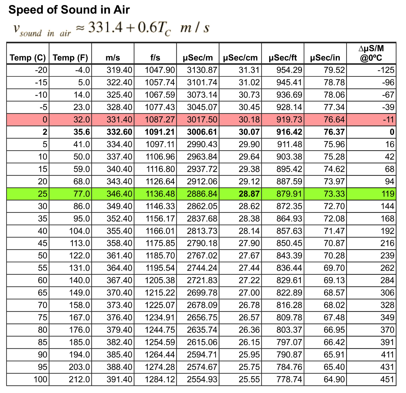
Referencing Table 1 above (click to view larger image), at 0° C, the formula simplifies to 331.4 m/S. At 25° C, the speed of sound in air becomes 346.4 m/S. A difference of 15 cm! Hence the desire to apply temperature compensation based on the temperature of the air the the sonar pulse is traveling through.
The POLAROID 6500 Sonar Module: The POLAROID sonar module operates on a “time of flight” principle. The module uses a simple interface; +5 volts, Ground, INIT and ECHO. With power applied, the INIT signal is driven high by a controller. The controller then looks for the ECHO signal to be driven high. That is, the controller times the round-trip duration from the start of the sonar “ping” (INIT pin) to the time the “ping” echo is detected (ECHO pin). The image to the right illustrates the timing. Click on the image for larger view.
Calculating distance to an object: Ambient air temperature aside, calculating the distance to an object using the sonar technique requires capturing the “time of flight” to and from the object. To capture the “time of flight”, simply find the difference in time between the leading edge of the sonar’s INIT pulse and the leading edge of the sonar’s ECHO signal. Take that amount and divide by two (2) to get the one-way time duration to the object then use the result to calculate in metres, centimetres, feet or inches (referring to Table 1 above for a quick reference).
Calculating distance to an object with temperature compensation: Using the above formula, simply plug in the temperature for “T”, multiply it by 0.6 and add to the 331.4 m/S. In most all of the ARDUINO projects with temperature compensation I have seen online (reference the links above), the mathematical formula is applied for each sonar and temperature reading taken. These calculations are easy enough to do in ‘C’ using floating point variables and calculations but it does take up program and data memory, which is fine for an ARDUINO UNO using the ATmega328p with 32KB of program memory available. But for the ATtiny2313 with only 2KB of program memory available, its a different matter as there are other support routines that need to fit into the 2KB of program memory.
Author’s chosen method of “time of flight” calculation: The original project from 2009 used a AT90S2313, which relied upon an external crystal oscillator for timing. An 8 MHz external crystal could have been used but 4 MHz was chosen instead. The main reason was due to the limited TIMER0 and TIMER1 prescaler options of the system oscillator; divide by 8, 64, 256 or 1024. With an 8 MHz oscillator, 1 uS TIMER1 counter increments were possible using the divide by 8 prescaler. With a 4 MHz oscillator, 2 uS TIMER1 counter increments were possible, which would yield the actual “time of flight” to (or from) the object. Recall that the “time of flight” from the sonar module includes the time to and from the object, which must be divided by two (2) to obtain the actual distance to the object. Note that the ATtiny2313 has a built-in 8 MHz (and 4 MHz) RC oscillator, which provides a frequency within ± 10% of the nominal frequency. Since the external 4 MHz crystal was already on the PCB and it’s frequency error was measured at less that 0.001%, it was preferred over the internal RC oscillator.
Author’s chosen method of temperature compensation: At the early design phase of this project, a spreadsheet was created that calculated the speed of sound in air at various temperatures and for various units of distance measurements. For the temperature compensation update, a table was added (reference Table 2) that does the same but also calculates the difference in time (uS/m) between 2° C and temperatures ranging between -10° C and 44° C. 2° C was chosen as the reference point because integer math is being used and 2° C is the next closest value above the integer divisor of 30, which minimizes calculation errors.

The table data was added to the assembly code as a 2×2 array of values stored in program memory to be used as a look-up table (LUT). The LUT consists of the temperature and the offset from 2° C that needed to be added to the sonars “time of flight” to attain a reading as if it was taken at 2° C. Because integer math is being used, there will be minor inaccuracies due to the divisor (uSec/cm for instance) being rounded to the nearest integer. Using a software window comparator function (same as the ATtiny Fan Controller Project ), finding the current temperature in the table will return the offset to use. The LUT code is shown below.
;=========================================
; Temperature Compensation Look-up Table
;	Col: 1 = Temperature in ºC
;		 2 = μS offset
;
DS18xLUT:
	.db	-10,-67		;0xbd, 0xf6
	.db	-8,-56		;0xc8, 0xf8
	.db	-6,-45		;0xd3, 0xfa
	.db	-4,-33		;0xdf, 0xfc
	.db	-2,-22		;0xea, 0xfe
	.db	0,-11		;0xf5, 0x00
	.db	2,0			;0x00, 0x02
	.db	4,10			;0x0a, 0x04
	.db	6,21			;0x15, 0x06
	.db	8,32			;0x20, 0x08
	.db	10,42		;0x2a, 0x0a
	.db	12,53		;0x35, 0x0c
	.db	14,63		;0x3f, 0x0e
	.db	16,74		;0x4a, 0x10
	.db	18,84		;0x54, 0x12
	.db	20,94		;0x5e, 0x14
	.db	22,104		;0x68, 0x16
	.db	24,114		;0x72, 0x18
	.db	26,124		;0x7c, 0x1a
	.db	28,134		;0x86, 0x1c
	.db	30,144		;0x90, 0x1e
	.db	32,154		;0x9a, 0x20
	.db	34,164		;0xa4, 0x22
	.db	36,173		;0xad, 0x24
	.db	38,183		;0xb7, 0x26
	.db	40,192		;0xc0, 0x28
	.db	42,202		;0xca, 0x2a
	.db	44,211		;0xd3, 0x2c
Component Selection

Microcontroller Unit: The heart of the original design was the ATMEL AT90S2313. However, the ATMEL/MICROCHIP ATtiny2313 was recently used to replace the AT90S2313. The ATtiny2313 is a drop-in replacement but also includes a internal 8 MHz R/C oscillator and a Universal Serial Interface (USI) peripheral that can be programmed to act as an SPI, I2C or 2nd UART interface. The ATtiny2313 comes in a 20-pin DIP package and contains 2048 bytes of FLASH program memory, 128 bytes of RAM and 128 bytes of EEPROM. As an FAE (Field Applications Engineer) from 1998 to 2001, ATMEL was one of my support lines. Other than being a newer part, switching to the ATtiny2313 did not gain me any extra functions over the AT90S2313.

Sonar Module: The second most important component is the sonar ranging module. I chose the POLAROID 6500 Series Sonar Ranging Module because I have two (2) of these units that I acquired as samples back in the mid 1990’s. The module interface requires only four (4) pins; +5V, GND, INIT and ECHO. The datasheet states that the module can accurately measure distances from 6 inches to 35 feet with a typical accuracy of ±1% of the reading over the entire range using a 50 kHz Electrostatic Ultrasonic Transducer. Note: The ECHO output is “open-collector” and must be pulled to VCC through a 4.7Ω K resistor.

Another popular hobbyist ultrasonic ranging sensor to enter the market is the HC-SR04 (left photo), which can be acquired for ~ US$2. There are lots of ARDUINO projects floating around on “the net” that do exactly what the AVR Sonar project does. Most of them using the HC-SR04 module. As an alternative, the HC-SR04 could also be used.
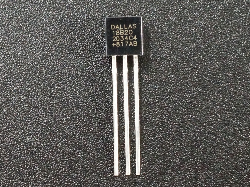
Temperature Sensor: There are several methods to measure temperature. All of them are analog in nature but the method to interface varies between analog and digital. Neither the AT90S2313 nor the ATtiny2313 have an analog-to-digital converter (ADC) on them, so using an analog interface to a device such as a thermistor or an on-chip temperature sensor is not possible. Therefore, only devices with digital interfaces are possible. Among these are the two (2) most popular hobbyist devices; the DHT-20 series, which uses a proprietary single wire interface protocol and the DALLAS DS18xx Series. I chose the DS18B20 (the MAXIM MAX31820 is the same device), which uses the published 1-Wire protocol. In my stock I also had a few DALLAS DS1821 “Digital Thermostat” devices. The DS1821 has a mode where the device will continually take temperature measurements and store them in it’s internal “scratchpad RAM”, whereas the DS18B20 must be told to convert, which can take anywhere from 100 mS to 750 mS depending on the selected resolution of 9 – 12 bits. Both devices give a direct reading in degrees Celsius. One word of caution: I acquired some DS18B20 parts from an eBay vendor for ~ US$0.99 each. MOUSER and DIGIKEY sell them for ~ US$7.00. With such a large difference in price, I suspected that the eBay versions are Chinese counterfeits. In testing, I found that with the parts I ordered, in setting the various resolutions, which per the datasheet, directly affects the conversion time, I found there is NO DIFFERENCE in the conversion time (always ~ 450 mS). So I am fairly certain the DS18B20‘s acquired from Chinese sources ARE counterfeits. Other than that, the Chinese counterfeits seem to work properly, including issuing ‘0’ on the Dq pin during read time slots while a conversion is in process.
Light Sensor: Since the AVR Sonar was going to be attached to the rear wall of the garage and the garage door may be open for hours at a time, I didn’t want the sonar to be taking readings 24 hours a day for 7 days a week. I decided that a means to detect either sunlight or any other ambient light source would be a good method to know when to take and display readings. In my stock, I had a few photo-transistors. Most don’t have part numbers on them, so I had to determine what the pin out was. The photo-transistor I used was very light-sensitive, so I had to use a large base biasing resistor to decrease the sensitivity and another transistor to provide level-shifting to the ATtiny2313‘s digital input.
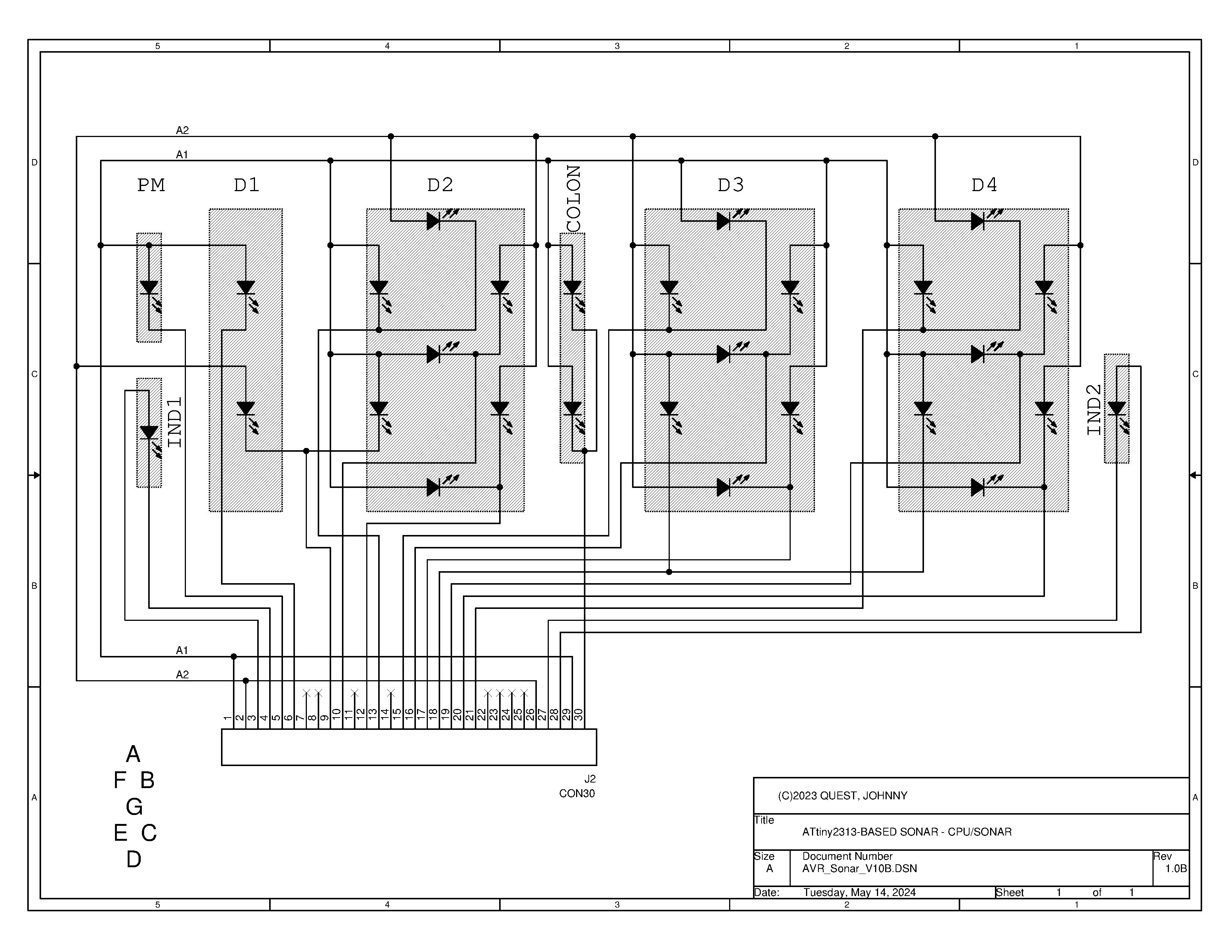
LED Display: At the time this project was designed in 2009, LCD and TFT displays were not readily available for a reasonable cost. At least 3 digits would be required to display centimetres or inches up to “999”. Years ago an old LED clock-radio was gutted and the LED display board was kept. Anyone that has ever worked with one of these old clock-radio LED displays knows that they are multiplexed displays BUT they typically have fewer anode/cathode pins than single LED displays, which reduces the pin-out of the clock Integrated Circuit. This particular display, a TOSHIBA TLR2198, has 0.6″ tall digits and uses two (2) anodes to drive 3½ digits, the colons and the AM/PM indicators. More about the software interfacing to the LED display is in this section.

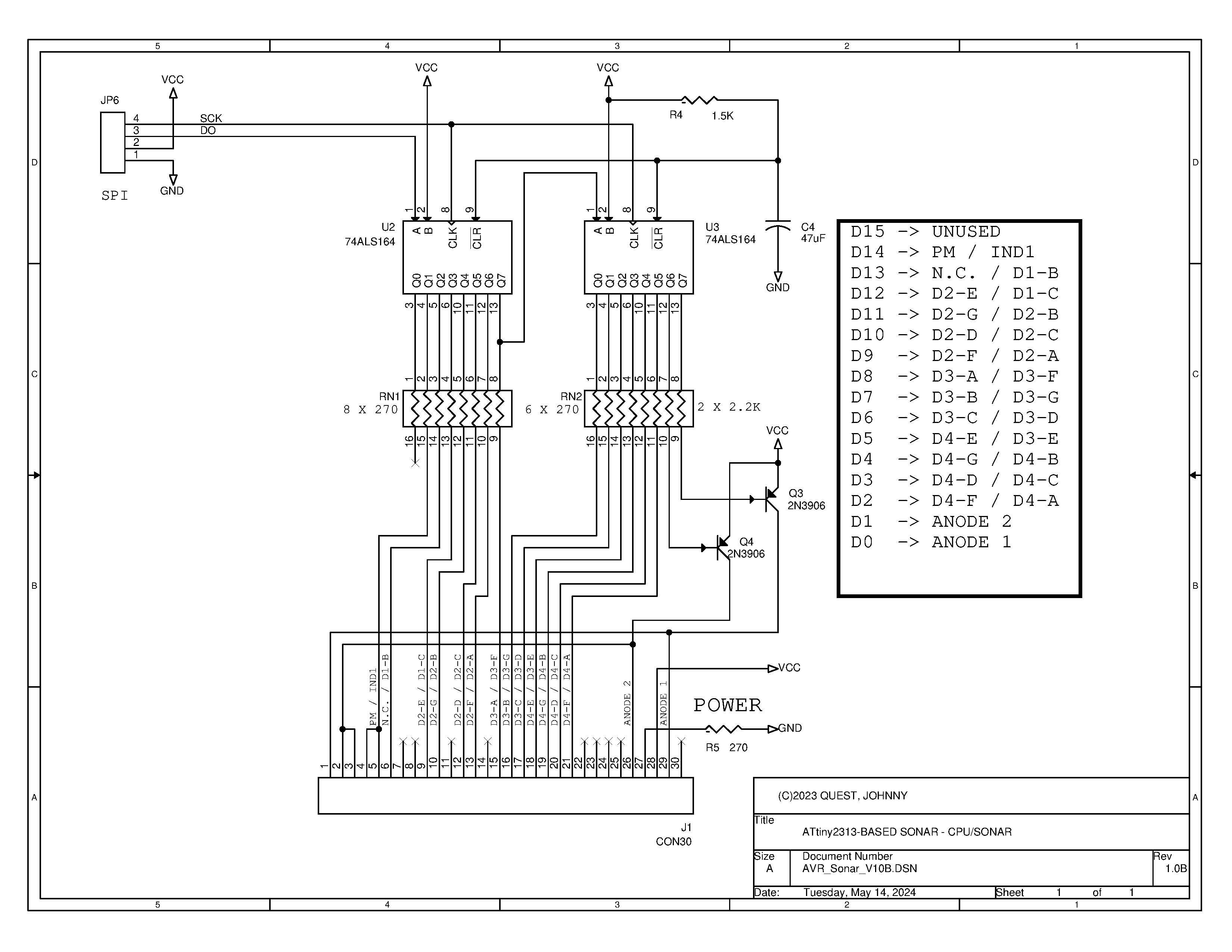
LED Display Interface: The ATtiny2313 doesn’t have enough pins to drive the TOSHIBA TLR2198 LED display, so daisy-chaining two (2) 74LS164 “8-bit Parallel Out Serial Shift Registers” into a 16-bit output port accomplished the task of driving the anodes and segments of the display. The original design with the AT90S2313 used a software (bit-banging) SPI interface to send data to the display shift registers. The ATtiny2313 has the Universal Serial Interface (USI), which can be configured as a hardware SPI interface. In this code update to version 1.2, the choice was made to write software to use the USI as the SPI interface to the display. The support code difference between the hardware SPI and the software SPI is an additional 2 bytes.
Power Supply: A 9 volt/1 amp “wall-wart” power supply is used to provide the overall power to the AVR Sonar. Internally, all electronic components and modules use a supply voltage of 5 volts. The current requirements for the AVR Sonar are mainly comprised of the ATtiny2313, the TOSHIBA TLR2198 LED display with all segments active (21 at ~4 mA/segment =~ 85 mA), two (2) 74LS164 shift registers and the POLAROID 6500 Series Sonar Ranging Module. The datasheet for the POLAROID 6500 Series Sonar Ranging Module states that a surge current of up to 2 amps can be drawn from the power supply during the transmit period, which is less than 1 mS. Therefore, a power supply filter capacitor of ~330 uF will minimize the surge current. A single LM7805 voltage regulator in a TO-220 package mounted on a heat-sink was chosen for the voltage regulator function. The actual run current when in standby mode is ~ 100 ma. Nearly 175 mA when the sonar and LED digits are active.
Controller Software: The software written for the AVR Sonar project is custom. Although GNU ‘C’ for the AVR was available in 2009, it wasn’t something I dabbled with much. Also, with only 2K bytes of program memory available, I didn’t think any ‘C’ program with this functionality would fit! Besides, I’ve always enjoyed programming the 8-bit AVR series in assembly language. [ AttoBASIC is one such project that is completely programmed in assembly language. ] For testing and debugging, I used an AVR Dragon with AVR STUDIO v4.19 along with it’s software simulator.
Other Products using the POLAROID 6500 Sonar Module
Several years before I designed the AVR Sonar, I was given a Christmas gift. A RADIO SHACK “Electronic Tape Measure“. It uses the same POLAROID 6500 Sonar Ranging Transducer as I am using. I still have the unit and it still works! Below are images of the product from an eBay listing.


Electronic Circuitry Design and Layout
With the component selections finished, I composed the schematic, which consists of three (3) pages. The interface connections to the ATtiny2313 are simple; sonar module, UART, SPI for the display, light detector and DS18B20 temperature sensor. In the images below, the left image is the controller board, the middle image is the TOSHIBA TLR2198 LED display module and the right image is the SPI shift-register interface to the TOSHIBA TLR2198 LED display. Click on each image to see the larger view. Click here for the PDF version of the schematic.

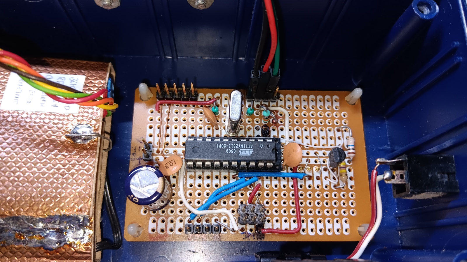
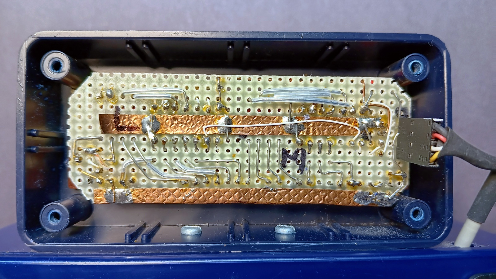
Main PCB: The final design resulted in mounting the ATtiny2313 and headers on a 3″ x 4″ piece of perforated bread board. All components and connections are hand-wired and soldered. The original layout used shared header pins for the SPI interface to the display or serial data from the UART. For the design update, I chose to separate the functions onto separate headers for two (2) reasons; 1) the USI interface uses different pins than I chose for the software SPI and 2) for monitoring purposes, I want to add an HC-05 Bluetooth serial port protocol module that interfaces with the ATtiny2313‘s UART. Because the POLAROID 6500 Series Sonar Ranging Module creates a 400 volt charge during transmission, I wrapped it in cardboard and copper foil tape for EMI isolation, which can be seen to the left of the main PCB. The main PCB and sonar module are mounted in a plastic project box. The light sensor and temperature sensor are mounted on the solder side of the main PCB and protrude through a hole in the plastic case. Click on the image to the right for a larger view.
LED Display Interface PCB: The final design resulted in mounting the two (2) 74LS164 shift registers and LED current limiting resistors on a 5″ x 1.5″ piece of perforated bread board. All components and connections are hand-wired and soldered. A piece of copper tape was run down the center of the 74LS164 shift registers to use as a ground plane. Regrettably, a photo of the component side of the PCB was not taken. The display interface board and LED display are mounted in a small plastic project box, which is bolted to the main project enclosure. Click on the image to the right for a larger view.
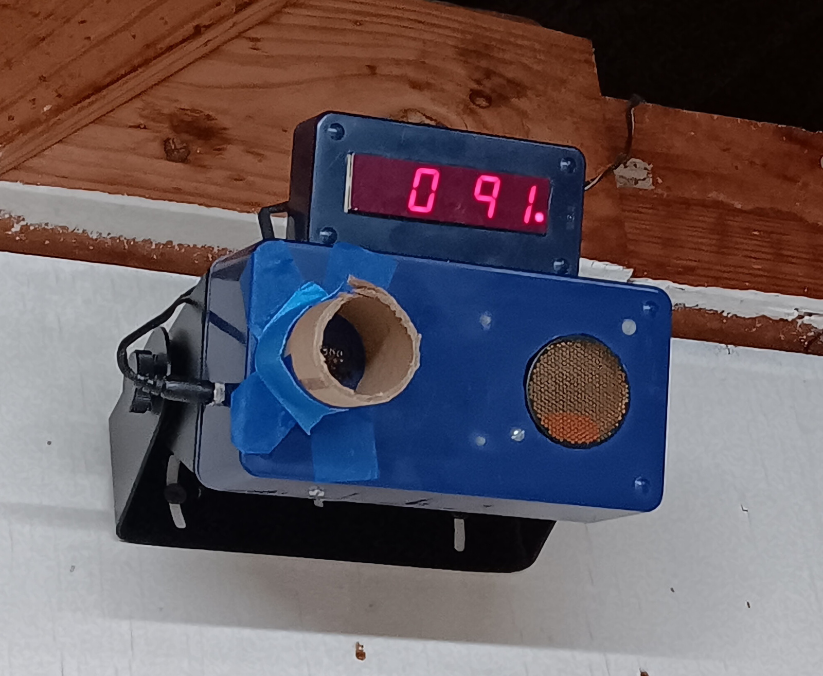
The left photo below shows the main enclosure and the display enclosure bolted together. The right photo below shows the AVR Sonar mounted on the garage wall in the NE Alabama dwelling (reading 91 centimetres). There is a square hole cut in the enclosure on the left that is for the light detector and temperature sensor. The cardboard tube was added as a “visor” to block out excessive light in the NE Alabama garage that has a window on the East wall. The excess light during the day kept the sonar active all day.

Software Design
In designing the software, the ATtiny2313‘s internal peripherals were taken advantage of. They consist of 1 @ 8-bit timer, 1 @ 16-bit timer with input capture, the USI (as the SPI interface), a watchdog timer and low power sleep mode.
8-bit Timer0: Is used as a general purpose timer that generates an interrupt every 15.625 mS. Its purpose is to multiplex the LED display and perform all required processing. It also decrements and checks the temperature reading timer and the sonar trigger timer.
16-bit Timer1: Is used as a capture source. It is set to run at 2 us per count, which is captured into the ICP register when the sonar’s ECHO signal goes high.
Universal Serial Interface (USI): Is configured as an SPI interface to the off-board LED display. The AVR319 application note explains the method of configuring the USI as an SPI interface.
Watchdog Timer (WDT): Is used to generate a RESET to the ATtiny2313 if the WDT is not reset by code within 250 mS.
USART: If the SIO routines are enabled, use the USART to send status information after every sonar “ping”.
Changes between the AT90S2313 and ATtiny2313: referring to the AVR091 application note, in addition to the hardware USI and on-chip debugging interface (DebugWIRE®) being added, the LPM instruction was also given two (2) more modes of operation; LPM reg, Z and LPM reg, Z+. Both instruction enhancements were used in the update to the AVR Sonar code, which yielded a code savings of 32 bytes.
The software is designed to work within an interrupt structured flow. In other words, all events are serviced by interrupts. There are two primary interrupt sources; Timer 0 and Timer 1 in “input capture” mode (ICP). When an interrupt is not being serviced, the ATtiny2313 is in low-power (idle) sleep mode. The main program loop consists of only four (4) instructions (below).
In the AVR Sonar software, there are two (2) modes of operation; light mode and dark mode.
MAIN1:
	sei							;restore interrupts
	sleep						;night-night!
	nop							;for benefit of the SLEEP instruction
	rjmp	MAIN1				;loop forever
Interrupt Sources: Timer 0 is the main interrupt source and is set to interrupt the ATtiny2313 every 15.625 mS (64 Hz). This interrupt service routine is the “heartbeat” of the AVR Sonar and processes all inputs and outputs. It’s primary task is to multiplex the data on the LED display via the SPI interface at a rate of 32 refreshes per anode per second. The complete tasks are as follows:
- Timer 0 Interrupts every 15.625 ms.
- Update the display with the digit data held in the DispH and DispL registers. The DispH and DispL registers hold the active LED segment and anode data for the last distance reading or all segments off for display blanking.
- Decrement the temperature read timer; take a temperature reading if ‘0’, reload the temperature read timer.
- If dark detected, set “suspend” mode flag.
- If light is detected and “suspend” mode flag is cleared then …
- Decrement sonar trigger timer.
- If sonar trigger timer = 0 then
- Pre-load Timer 1’s counter register with the value of the constant TCNT1ld. Timer 1 will roll-over to ‘0’ when clock source is enabled.
- Set Timer 1 to input capture mode and enable clock source. The sonar ECHO signal will gate Timer 1 at 2 micro-seconds (uS) per count, which will capture the one-way “time of flight”. The resulting count will be the time to target in uS.
- Send sonar “ping” (set sonar INIT high).
- reload sonar trigger timer to 500 mS.
- If dark is detected, set “suspend” mode flag then …
- Update the display with the “blank” digit data held in the DispH and DispL registers.
- Decrement sonar trigger timer.
- If sonar trigger timer = 0 then clear “suspend” mode flag and reload sonar trigger timer to 120 seconds.
- Return from interrupt
- Timer 1 Interrupts on start of sonar ECHO pulse
- Capture the ECHO pulse width (the difference between the leading edge of INIT and the leading edge of ECHO), which is the “time of flight”.
- Apply temperature compensation to the measured “time of flight”.
- Calculate the distance (centimetres or inches).
- If same distance as last reading, decrement “GoodRead” counter, else reload “GoodRead” counter.
- If number of good reads = limit
- reload sonar trigger timer to 500 mS.
- set “suspend” mode flag.
- Convert the distance to multiplexed BCD format and store the result into the DispH and DispL registers
- Return from interrupt

LED Display Interfacing: If one does not recognize the meaning of the term “multiplexed display” then first refer to this explanation on multiplexed displays.
As previously mentioned, the AVR Sonar project uses a TOSHIBA TLR2198 clock display. Like most LED clock displays of the era, multiple anodes are used to access multiple digits in the display. The TLR2198 has two (2) anodes. The schematic above (click on the image for a larger view) shows the common wiring between the segments of each display digit and the two (2) anodes. The AVR Sonar software uses a look-up table (LUT) method to encode the active segments for each digit position for each anode. The pin-out for the shift registers to the display was chosen so that the anode data is in the last two (2) bit positions to be shifted in. In that way, display flickering is minimized during display updates. The routine BCD2DPLX converts the BCD equivalent stored in the DispH and DispL registers to a 16-bit value, which is sent out the SPI port to the two (2) cascaded 74LS164 shift registers, whose outputs drive the individual digit segments and the anodes. Refer to page 3 of the schematic for specific hardware connections. Since each of the digits has segments attached to both anodes, each digit’s segments must be alternately multiplexed with each anode to create a fully illuminated digit. In order to do this and to also blank the display, each anode is also driven separately. A LUT excerpt for displaying ‘0’ on the right-most digit is shown below. A ‘0’ in a bit position enables the particular segment or anode. The entire table consumes 122 bytes of program memory, nearly 6% of the entire program memory.
LEDDL_0:
;ANODE 1:	NPDDDDDDDDDDDDAA
;			AM12222333444421
;			  BEGDFABCEGDF
	.dw	  0b1111111111010010	;Seg ABCDEF
;ANODE 2:	NINDDDDDDDDDDDAA
;			ANA1222333344421
;			 1 CBCAFGDEBCA
	.dw	  0b1111111111100001

Overall code size: With all optional code modules enabled; DS18B20 with 1-Wire support, USI support and SIO with ASCII message strings, the code size is 1934 bytes, which takes up 94.4% of the 2K bytes of program memory available in the ATtiny2313.
Optional Logging Feature

With the SIO code module enabled, the AVR Sonar emits status information with each sonar “ping”. For easier viewing, an HC-06 Bluetooth module was connected to the USART interface and temporarily installed in the AVR Sonar enclosure. The HC-06 Bluetooth module was preset for 19.2K baud and then paired with my cell phone. [ 19.2K baud was chosen because the bit error is 0.6%, whereas a higher baud rate would introduce up to a 7% bit error, which confused the HC-06 Bluetooth module ] The ANDROID application named “Bluetooth Serial Terminal” was installed on my cell phone and when connected to the HC-06 Bluetooth module, allows me to monitor the status messages. The images below are screenshots that show the status message, one for each sonar “ping”. The data emitted is; temperature, timing offset (from 2° C), captured echo “time of flight” and the distance calculated.


Mounting the AVR Sonar
The mechanical mount used was a RADIO SHACK bookshelf speaker wall mount bracket. The bracket can be set to different angles in 22.5° increments. The AVR Sonar’s plastic enclosure was exactly the size of the wall bracket, so it was a perfect fit!
Performance and Insights
The updated features of the AVR Sonar have been running for a week now. I’ve seen temperatures range 24° C to 32° C with only a ± 1 cm variation over that limited temperature range. I am looking forward to winter season to see just how effective the temperature compensation method will work.
Project Files
The project files are enclosed in the ZIP file below. The free version of WORDPRESS does not allow me to upload ZIP files, so I have to rename them with a PDF extension. Click on the link below to download the file and rename it without the PDF extension before extracting files from it.
AVR Sonar V1.2 Project files
Closing thoughts
I really enjoyed working on the hardware and software update of this project. I found the DS18B20 temperature sensor and it’s addition to the hardware base very easy to work with. Admittedly, it took more time than I imagined to implement the hardware and software modifications but that was mostly due to porting the 1-Wire code, which was originally written for AttoBASIC. I ran into timing issues with the 1-Wire protocol “read time slots“, which made the device un-readable. To compound the issue during debugging, using DebugWIRE® on the ATtiny2313 caused unrealistic instruction execution delays in the execution of timing loops used in the 1-Wire support code, which made them slower than real-time. This issue did not show up on the AVR parts that use the JTAG interface for debugging. I never discovered the cause of the execution delays but I suspect that it was because of the serial nature of the DebugWIRE® interface. I resolved the timing issues by more strictly adhering to MAXIM’s AN126 “1-Wire Communication Through Software” application note. I updated the code in AttoBASIC and retested proper operation on the ATtiny84, ATtiny85 and ATmega328p parts.
This completes the project log for the update to the AVR Sonar.
Peace and blessings,
Johnny Quest
